Interrupt
Schematic Symbol : Interrupt
Simcode : 12001
Interrupt is a request for attention from the microcontroller. When the microcontroller receives an interrupt, it suspends its current operations, saves the status of its work, and transfers control to a special routine known as an interrupt handler, which contains the instructions for dealing with the particular situation that caused the interrupt. Interrupts in EDWinXP can be generated by Interrupt Generator.
This instrument model is grouped under ‘Instruments’ category in the Schematic Browser.
How to Simulate:
Invoke Mixed Mode simulator from EDWinXP Schematic Editor -> Preferences menu. Physical connections if any are made to the interrupt symbol and logic waveform marker is placed to view the waveform.

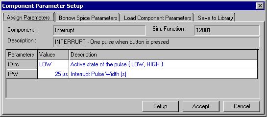
The simulation parameters are then assigned by selecting Tools menu-> Instruments-> Component Properties->Change Simulation
Parameter and then clicking on the model.

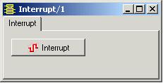
The pulse width and active state of the pulse are specified and on clicking Setup, an Interrupt window pops up. This window can be resized as required.

To simulate the model, select Simulation menu -> Analysis -> Transient analysis OR Oscillograph OR Logic Analyzer.
Each time the Interrupt button is clicked, a pulse with the specified active state and pulse width will be generated.

Click here to view other Instrumental Models