3 Dimension
Introduction to 3D
 View Video
Designed electronic circuits (PCB) are usually housed inside
cabinets or any intricate structures where spacing between different boards
placed has to be dealt with prudently. Working in 3D environment facilitates
optical design check. It provides an in-depth analysis of the board density
and a realistic view of a designed PCB.
The concept of 3D has been incorporated into Layout
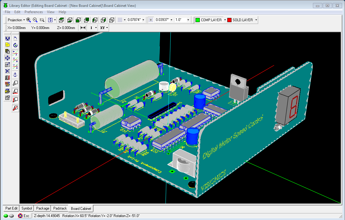
Editor and Library Editor especially for package creation.
Layout Editor allows only viewing the board in 3D; no editing can be done on
the components or traces. But Library Editor allows editing packages and cabinets.
Tools have been provided to view the board and package from various directions
and from different angles.
Let us have a look at how 3D has been implemented in Layout & Library Editors.

3D in Layout Editor
Layout Editor is provided with two tools namely 3D Board Viewer
and 3D Trace Viewer. These tools may be activated from the menu Tools or from
Tools toolbar. 3D View Control dialog contains useful tools to control working
in 3D environment. These can also be invoked from Layout Viewer.
3D Board Viewer
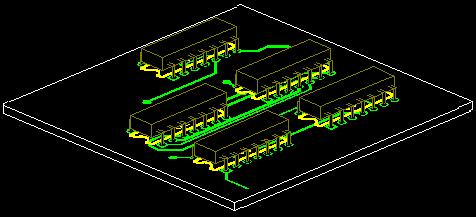
3D Board Viewer gives a real life view of the designed board
in various perspectives and directions. It gives idea on how the components
are located, whether there is risk of friction between components due to their
height and shape, the side on which components are placed, etc. This helps to
take any design changes if required. Thus it provides a 3D view of the entire
board in any of the X, Y or Z planes from different angles. It also provides
the facility to view the board from different directions namely north, south,
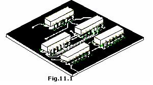
east, west, etc.Fig.11.1 shows 3D view of a finished board inclined at 45º
along X - axis and –65º along Y-axis.

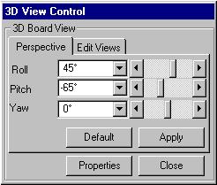
When clicked on  3D board Viewer to get a 3D view of the loaded board a 3D View Control dialog
pops up, which assists in aligning the board in different angles.

Fig.11.2
In Layout Editor 3D Board Viewer can be invoked from menu Tools ->3D Board Viewer.
3D Board Viewer gives a real life view of the designed board in various perspectives and directions.
It gives idea on how the components are located, whether there is risk of friction between components
due to their height and shape, the side on which components are placed, etc. This helps to take any
design changes if required.
