The purpose of DXF import in EDWinXP is to bring in complicated mechanical features like board
outline and cutouts that may be easier created in AutoCAD. There are rules governing this import.
Geometrics representing outline and cutouts have to be closed shapes.
You have to create artwork file in the same way as from Gerber and then import it using Graphics
imports. Subsequently reconstruct those categories that are possible to reconstruct.
Graphics imported from Artwork Files may be directed to Graphic Import Categories in order to
allow proper identification and interpretation during edition and reconstruction phases. Normally
graphics defining traces, via or component pads are mixed in one import file. Categorized import
enables to extract relevant types of graphic elements from Artwork Files and store them in
dedicated places.
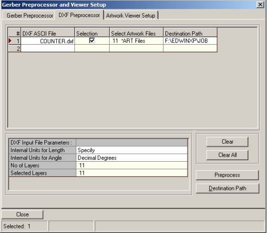
The DXF files can be transferred to Artwork files by the following
Fabrication manager → File→ Gerber viewer setup → DXF preprocessor → then browse the
DXF for conversion. Check the ‘selection’ option in the “Gerber Preprocessor and viewer setup”.
Click on ‘Preprocess’ inorder to generate the Artwork files.

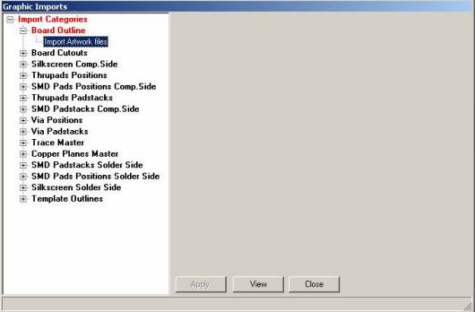
The process of graphic import can be executed as follows:
Tools → Graphic Imports → Import graphic item→ Select on Board outline→ Right click on
“Import Artwork file” →Add artwork file

a) Board Outline to import graphic elements needed for reconstruction of PCB outline.
b) Board Cutouts to import graphic elements needed for reconstruction of cutouts in the
PCB.
c) Silkscreen Comp. Side to import graphics element constituting silkscreen for Component
(Top) side of the PCB. This category may be used as a template for reconstruction of
components.
d) Thru-pads positions. Pad coordinates (flash D-codes) for Pin Mounted Devices may be
imported from Artwork Files. These coordinates are graphically represented in this
category and used as a template for reconstruction of PMD type of components. User
can also assign hole diameters to thru-pads positions (with same size aperture) in order
to reconstruct NC-Drill data.
e) SMD Pads Position Comp. Side. Pad coordinates (flash D-codes) of Surface Mounted
Devices placed on Component (Top) side of the PCB may be imported Artwork Files.
These coordinates are graphically represented in this category and used as a template
for reconstruction of SMD type of components.
f) Thru-pads Padstacks. Graphic elements constituting PMD pads may be imported to this
category. These elements may be edited for revision of artworks.
g) SMD Padstacks Comp. Side. Graphic elements constituting SMD pads located on
Component (top) side of the board may be imported to this category. These elements
may be edited for revision of artworks.
h) Via Positions. Pad coordinates (flash D-codes) are imported from Artwork Files. These
coordinates are graphically represented in this category and used as a template for
reconstruction of via holes. User can also assign hole diameters to via-hole positions
(with same size aperture) in order to reconstruct NC-Drill data.
i) Via Padstacks. Graphic elements constituting PMD pads may be imported to this
category and edited for revision of artworks.
j) Trace Master. Graphic elements constituting traces may be imported to this category and
used for reconstruction of physical connection on the board.
k) Copper Planes Master. Graphic elements imported to this category are used to
reconstruct copper planes and copper pour areas.
l) SMD Padstacks Solder Side. Graphic elements constituting SMD pads located on Solder
(bottom) side of the board may be imported to this category. These elements may be
edited for revision of artworks.
m) SMD Pads Position Solder. Side. Pad coordinates (flash D-codes) of Surface Mounted
Devices placed on Solder (bottom) side of the board may be imported Artwork Files.
These coordinates are graphically represented in this category and used as a template
for reconstruction of SMD type of components.
n) Silkscreen Solder Side to import graphics element constituting silkscreen for Solder
(bottom) side of the board. This category may be used as a template for reconstruction of
components.
o) Template Outlines. Graphic elements imported to this category may be used for
reconstruction of template outlines.
The components, traces, etc can be recreated from Tools → Graphic Imports → Reconstruct
from graphics, select on each item for recreating the Corresponding items can be recreated.