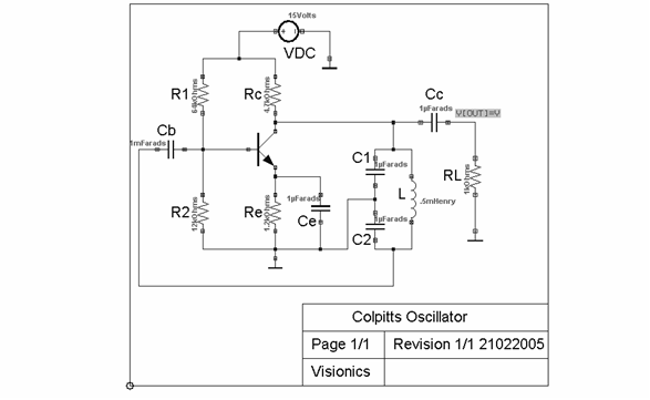
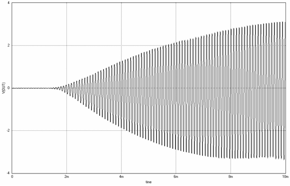
Colpitts Oscillator
Aim: -
To design and simulate a Colpitts Oscillator.
Components: -
|
Name
|
EDWin Components Used |
Description |
Number of components required |
| VDC |
VDC |
DC Voltage Source |
1 |
| GND |
SPL0 |
Ground |
3 |
| NPN |
BC107 |
Transistor |
1 |
| RES |
RC05 |
Resistor |
5 |
| C |
CASE-A600 |
Capacitor |
5 |
| L |
IND2012C |
Inductor |
1 |
Circuit Diagram: -

Procedure for creating schematic diagram and simulating it
1. Open EDWinXP x.xx from Start ->Programs->EDWinXP Main.
2. Invoke the Schematic editor by double clicking the Project ->Main page.
3. Choose EDSpice Simulator from Preferences Menu
Drawing the circuit diagram
1. The circuit can be drawn in the required page size like A4 (portrait, Landscape), A3 etc can be selected from Tools ->Page Format ->Define Page (first function tool).
Loading/Placing of components
Components can be loaded in the schematic page by selecting
1. View ->Toolbar ->Schematic View.
2. Select the option Browser from the Schematic View toolbar. Browser is displayed in the right hand side of the Schematic Editor.
3. In Browser, Select Resistors and choose Resistor, click on place button and place it on the screen. Similarly place Capacitor, transistor, Inductor from it group.
4. Select Ground from sources group and place it.
5. Select Voltage source from Sources group and place it.
6. The components can be placed in the grids with 100 mils (.1") and snap of 50 mils (.05")in the required position by relocation.
Routing Connections
The connection between components can be made by
1. Tools ->Connections ->Connect components (First Function tool) {Connect the wires from pin to pin according to the circuit diagram.} while asked for entering Net name, give suitable names
2. Select Tools ->Connections ->Connection properties ->Click on any connection and name it as required.
Giving values:
1. Select Simulation ->Preprocess
2. Select Tools ->Components ->Component properties ->Change simulation parameters ->Select any component and change it values.
Resistor : R1->64K, R2->12K, Rc->4.7K, Re->1.2K, RL->1K
Capacitor :C1->1uF, C2-> 1uF, Ce->1uF, Cc-> 1uF
For DC Voltage Source, Select the source function Properties as follows:
DC Transient analysis of the source - 15 Volts
Simulation using Instruments
Select Tools ->Instruments ->set wave form Contents ->Voltage waveform ->Click on net OUT and place the waveform marker as shown above.
Preprocess:
1. Select Simulation ->Preprocess
2. For setting up simulation time and analysis types, select Simulation ->Analysis.
3. In the window pos up, select Transient analysis from tree view.
4. Enter following values:
Results: Select waveform from drop down menu.
6. Expand the transient tree view and select waveform viewer, click on as marked.
8. Click on Run button to run Analysis
Page Notes (For creating Title Block)
For the placing of Title Block in a Schematic page, we use the page note property
Tools ->Page Notes ->Create Graphic item ->Create Text .
