AC Sweep Analysis
The circuit operating parameters have all been stabilized for the circuit
AMPLIF.EPB and set after the DC sweep analysis. Now we may calculate the
small-signal frequency response of the circuit assuming its current biasing. We
will not define any AC parameters for the active components like transistor -
the Simulator assumes their values calculated internally from the nonlinear
transistor model using its working point.
1. Before any further analysis is performed, compute the operating point again,
using Analysis menu (Refer Bias Point Calculation).
2. We will now have to define the AC Analysis input points.Right click and select the  AC IN+ option tool from the function tool
  Reference Points. Click the left mouse button at the “+” terminal of the Generator. We will see a text “IN+”, position this AC Input testpoint.
3. To define the AC Analysis output points, right click and select the  AC OUT+ option tool from the function tool
  Reference
Points. Click the left mouse button on the net connected between C2
and RL. We will see a text “OUT+”, position this AC output testpoint.
4. The AC testpoints IN- and OUT-, for AC input and output are by default assigned to ground net SPL0 and we need not define them except for special cases.
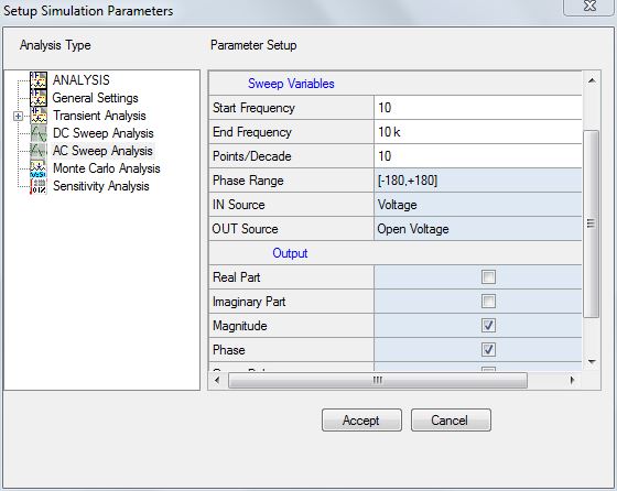
ine the fr5. We will now have to define the frequency sweep parameters. Click Analysis in the main menu. A window Setup Simulation Parameters opens with the option Analysis being highlighted on the left side of the window by default. Set the parameters by selecting
GENERAL SETTINGS from the tree view on the left side of the window. Now, select the
AC Sweep Analysis option.

Set the values for the following parameter as shown below.
Start Frequency 10 Hz
End Frequency 1 GHz
Points per Decade 10
Range of Phase [-180°, +180°]
IN source Voltage
OUT variable Open voltage
Output Magnitude, Phase, Group Delay.
6. We will observe that the AC simulation will analyze the circuit response for a frequency sweep from 10 Hz to 1 GHz (8 decades) with 10 points per decade - total 81 points. Phase shift is calculated within the range from -180° to +180°. An AC voltage input source is placed between IN+ and IN- net. An AC voltage is measured on the opened OUT+ and OUT- nets. The ratio Vout / Vin will be an output that is shown in three forms: magnitude, phase and group delay.
7. Click ACCEPT button to automatica7. Click ACCEPT button to automatically switch to Analysis option. Check
AC Sweep Analysis check box. Now click START button for
AC Simulation Pass to take place.
8. If Display Waveform is checked in the above dialog box, the output is displayed in the Waveform Viewer and the three curves depict the graphical dependency of the calculated Gain, Phase Shift and Group Delay from the frequency parameter. From this, we see that the lower unity-gain frequency is about 60 Hz, upper unity-gain frequency is about 50 MHz. Middle-frequency gain is about 40 dB.
We will save these results on the MIXSIM Numeric Data Output file named TUTOR_EX.MCR for further use by the Waveform Viewer. Select
File | Save in the Waveform Viewer menu. Specify the name of the file as tutor_ex and click
OK. Exit from the Waveform Viewer.
We can now test the circuit AC characteristics for another bias point. For example, with the RB2 set to its original value 20k ohms, do the following.
1. Right click and select the  Set Parameter
option tool from the function tool
  Set parameters/ models and set RB2 resistor to 20k value.
2. Click Analysis in the main menu and select the Analysis from the Setup Simulation Parameters dialog box that appears. Enable the
Bias Point Calculation check box in order to recompute the bias point for the design.
3. Enable AC Sweep Analysis check box after selecting the Analysis option in the Setup Simulation Parameters dialog box. Click the
ACCEPT button to start the AC analysis.
4. Display the AC Sweep diagram.
frequencies are now 180 Hz and 500 kHz, and the maximal gain is now about 24 dB. The original bias point gives a poor AC circuit response.
5. Exit from the Waveform Viewer.
6. Reset the value of resistor.