EDWinXP Features
General
- Refresh Project Library
- Automatic detection of updates
- Storing/restoring settings
- Remembering latest file path
- Text input dialog with preview
Refreshes the symbols, package, padstack and parts in the project library.
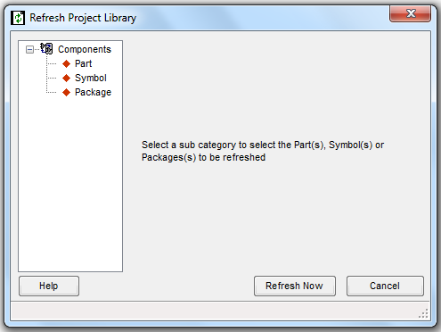
Select 'Refresh Project Library' from Project Explorer, The Refresh Project Library window appears as shown below . Select the sub category to select the parts , Symbols or Packages and click on Refresh Now button . Details of the components updated can be viewed in file viewer and can be saved for future references.
EDWinXP has been equipped with a function that automatically detects that updates are available and informs the user when program is invoked.
All current settings may be stored and then restored in case of reinstallation of EDWinXP.
Whenever disk file is opened for output and input the file open dialog redirects to the folder selected with previous opening of a file of the same type.
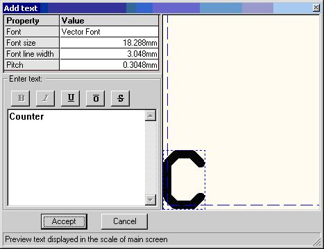
Several users wished that dialog for text input should show also text preview in the same form and size as on the graphic screen. The problem was in selecting proper text size in relation to the size of objects displayed on the main screen. In the new dialog, the first character of entered text is shown in preview screen in current scale of the main graphic screen. Text preview dialog has been added to all applications where there is a need for entering text. Additionally, any required text size may be also set directly in this dialog. Previously user could select only one of 15 preset sizes. Possibility to preset text sizes for all editors has been though retained in order to facilitate fast selection. It applies also to setting text sizes in all Property dialogs.
- Magnifying glass
- Coordinate Zoom
- "Ruler" cursor
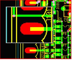
All editors have been equipped with movable "magnifying glass". This feature allows viewing portion of displayed image in 1, 2, 3 and 4 x magnifications.
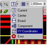
Possibility to focus display on entered X, Y-coordinates has been added to redraw modes in all editors.
Current cursor position is reciprocated in the ruler.
Schematic Editor
These two useful options for manual routing of wires (similar to those implemented previously in PCB Layout Editor) have been now added to Schematics Editor.This option allows the user to delete all existing bend points in the trace and start rerouting all over again.Click on this option and then click on any wire. The system will delete all existing bend points within the trace and the connection is ready to be rerouted
This feature allows for simplified creation of block diagrams of hierarchical circuits. There is no longer need to create block diagram elements using Library Editor since part descriptions and symbols are automatically created according to user’ s specification. Nevertheless, parts and symbols created for block diagram elements may be edited like any other library element and stored in the disk libraries for farther use.
Layout Editor
- Trace Length and Width Trimming
This feature allows inserting pattern of segments into selected trace in order to obtain exact specified length. The shape of the pattern, its amplitude and step length may be set as parameters for calculation of necessary number of steps. All user has to do is to select the suitable point in the trace where the pattern should be inserted. This is done interactively - the pattern (generated according to currently set parameters) is visible and follows cursor while it is moved along the trace. Parameters may be adjusted during this time until permanent insertion is confirmed by the mouse click
Trimming function works in three modes: trimming single trace to specified length, trimming two traces to the length of longer one and trimming net connection to specified length. In the latter mode, it is possible to see how changing of length and average trace width affects net's electrical properties (resistance, capacitance, inductance and impedance)
As further requested improvement, the current trace length is dynamically calculated while trace is manually routed or re-routed. - Automatic correction of selected clearance errors
Reporting of clearance errors have been improved by providing additional details of detected conflicts. The dialog presenting locations of conflicts is always visible (modal) while navigating from error to error. Focused errors are distinctly marked for exact identification.
Another new feature is automatic correction of selected clearance error. This function works in two modes. Error to correct may be selected by pointing corresponding marker on the screen. The program is now able to recognize exactly which traces are in conflict. The one that creates most conflicts is automatically rerouted. In other mode, the user may select any of conflicting traces and order its automatic rerouting. - Automatic clearance correction after routing and rerouting.
On-line clearance error check introduced in previous version reported detected errors while a trace was routed or re-routed and after these operations were completed. In version 1.60, the on-line clearance check feature has been strongly enhanced by automatic correction of all clearance errors caused by the last route or reroute operation. This function has several options. It may be specified that correction should be executed always when error are detected without asking. Alternatively, information that errors have been detected is displayed awaiting confirmation for executing correction. It is also possible to order that correction should apply to the last routed/rerouted trace or that this trace must be left unchanged and only other conflicting traces should be automatically rerouted.
- Automatic "trace project" feature
Pressing key combination, Shift A when a trace is manually routed or rerouted activates and deactivates automatic "trace project" function. Following happens, depending on currently executed operation:
" When a new trace is created and the function is ON, the program automatically routes clearance error free connection from the last inserted point to current cursor position. Cursor movement changes this so-called "trace project" to reroute dynamically depending on obstacles encountered on the way. Mouse click confirms that trace project to this point is accepted and subsequent trace project starts to be routed from this point. Even if the route suggested by trace project is not accepted, the feature may be used to seek best way for manual routing. It is possible to alternate (by Shift A) between the modes and route some parts of the trace manually and some parts automatically. " When a trace point or segment is relocated, and the automatic trace project function is ON, the program reroutes preceding and following segments of the trace, starting in both directions from current cursor position. Using option "rip-up before reroute" allows in this case rerouting of entire connection between two nodes.
Project trace is routed according to design rules and auto-routing parameters currently set for the net. - Auto dimensioning of packages and padstacks
Users who produce boards on order often need to document library elements created for each design, even in printed form. For this purpose, dimensioning of packages and padstacks has been implanted in version 1.60. Tables with dimensioning data in following form are created fully automatically after switching to this mode while editing packages in Library Editor or viewing them in Package Viewer
- Shortcut to copper check added to flood test
Checking for short cuts to copper pour areas were in previous version cumbersome because it required starting Fabrication Manager and use of function provided for editing artworks. Now, the flood test for copper pour connectivity that has been implemented in previous version has been enhanced to include also shortcut check. In this manner, all layout design testing functions are finally grouped in one application.
- Identification of Selected pin in Layout through property window
Select the function tool Component Property and click on a component pin to get the component property window with the selected pin highlighted in the left pane
- CutOut Creation
This option tool may be used to define cutouts on the board. Cutouts are areas where a portion of the board is removed for mechanical purposes. Cutouts may be created in different shapes and sizes. Contact points may be used to place to create cutouts. Select this option from Layout Editor->Tools-> Board Outline->Define Outline.and click on the workspace within the board. A line tags to the cursor. Move the cursor to the required point and click. Similarly, create all the vertices of the cutout. Use F4 or END key to complete the operation.
- Auto Connect Functions
Auto-connect tools in Layout Editor are complement to manual trace routing tools. These auto-connect functions work directly on items in the project database. Execution time depends very much on the complexity of the board. Whether routing task is completed successfully depends on topology of currently existing connections. The Auto connect tools come under Tools | Connections | Auto Connect Traces are:
Auto Connect Node Pair : Routing connection from node to node.
Auto Connect Net: Routing connections for all nodes in selected net with the option to keep pre-routed traces unaltered.
Auto Connect Net Element: Routing connection from selected net element (existing trace or node) to closest located element in the same net.
Auto Lead-Out from Net Element: Routing lead-out traces from component nodes.
Auto Clear Component Zone: Clearing a zone around a component(s) and re-routing all traces not connected to this component outside of the zone boundaries
Auto Remove Vias: Removing redundant via holes on the whole board
Auto Miter: Mitering all traces on the board in 45 degrees
- Tapered trace segments Any trace segment may be assigned different widths at the start and at the end. When property "Tapered" is set at the beginning of a segment, it will produce following results: If the width at the end of a segment is smaller then at the beginning, then the segment will taper down gradually along its all length. In opposite case, such a segment will taper up from smaller to bigger width. In version 1.70, this new feature has been used in several semi-automatic and automatic tools. User may for example force selected or all segments in any trace to taper whenever there is a change of width from segment to segment. This function creates smooth change of width in cases when thicker trace must be routed between pads.
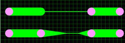
On request, all or selected trace segments may be automatically tapered to adjust to the size of the pad to which they are connected:
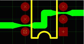
As seen on the picture above, ordering the thin trace segment to taper to a pad with bigger diameter produces similar results as creating "tear drop" pads by adding copper elements (a method used in previous versions of EDWinXP). The advantage of tapering is that there is no need to add any loose copper elements. The old method for creating "tear drop" pads has been retained for compatibility reasons .
