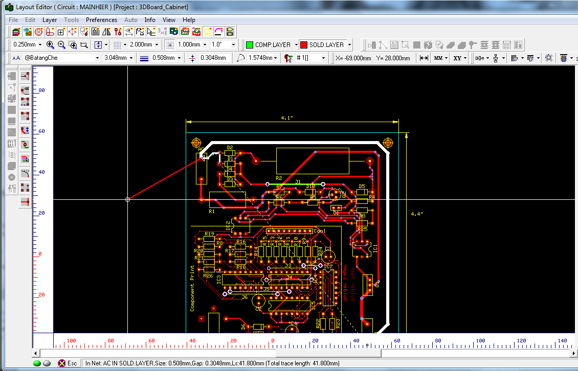
Layout Editor
Schematic Editor now contains an auto-generated title block into which user can insert project name, company, paper size etc.
Working
- Select Statistics from
Info menu in Layout Editor. A window will pop-up as given below

- If you want to change the total trace length from inches to millimeters, change the Unit option from View menu from Layout Editor.
Working
- Select View Port option from View menu in Layout Editor.
- Click
 option from Redraw to view the actual size of the board
- Default menu options in Viewer.

Instead of burying all vias , users can now bury via in a selective manner with respect to the Start and End Layer. An Input Screen is provided for bury via.

Similar to traces and Net, a property form for a Via is now displayed while clicking a particular Via when the property via option tool is checked. Pad stack type for a via can now be changed directly from the property form.


Now along with the node, traces in the net gets highlighted when routing. So user will able to see the the net they are connecting.
Enhancement
The total design time has been added to the Statistics menu.
Working
- Select Statistics from Info menu in Layout Editor. A window will pop-up as given below

Working
- From Auto menu in Layout Editor, select Parallel Routing option. This will enable the Parallel routing mode. Enable Connections – Route.
- Earlier for Parallel routing of traces depress the key combination Shift + E prior to selecting a starting pad of a traces set. This enables the mode for blocking several pins. Selecting the pins will enable parallel routing window where you can specify the routing space. Specify the spacing and click on Accept button.

- The pad that is closest to origin of the blocking rectangle is taken as starting point of the leading trace in parallel group. The leading trace may be routed and other traces will follow it
parallel with specified spacing.
- After arriving to final destination for the leading trace, it can be connected in normal fashion. When leading trace is connected, the next unconnected is taken as the leading and parallel routing continues until all in the bunch been connected or operation aborted by
ESC

- In some instances, it may be needed to narrow the spacing between traces to get through a tight spot. In such cases, routing of the leading trace and parallels may be terminated at any point with F4 key. With option “Allow T- connections” ON, lose ends of previously routed parallels may be grabbed in similar fashions as pads by blocking and new spacing (smaller or bigger) is applied.
Working
- Enable Connections in Tools menu, select
Route from Connections. Then select Interactive Routing option from
Auto menu.
- Select the pins of required components and click and drag it (earlier it has done by
Shift+A) as shown below

Working
- Select Tools menu of Layout Editor and click 3D Board Viewer.
- You will see the 3D view of the layout with enabled 'Use components own color' option.

Working
- Select 'Tear drop pads' from Preferences

- A pop-up window will appear as given below.
