Parallel Pattern with Interrupt
Schematic Symbol : PPatternINT
Simcode : 12006
This model generates a parallel pattern along with an interrupt pulse. The data bytes stored inside the memory of the model appears at the output, byte by byte, with an interrupt pulse of specified duration between each byte. The duration after which the interrupt pulse appears for each byte transmitted depends on the setup time specified.
This instrument model is grouped under ‘Instruments’ category in the Schematic Browser.
How to simulate:
Invoke Mixed Mode simulator from EDWinXP Schematic Editor -> Preferences menu. Physical connections if any are made to the parallel pattern with interrupt symbol and logic waveform marker is placed to view the waveform.

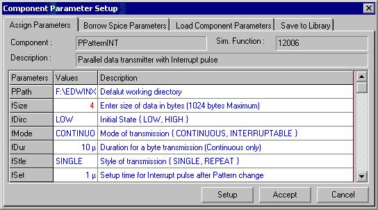
The simulation parameters are then assigned by selecting Tools menu-> Instruments-> Component Properties->Change Simulation
Parameter and then clicking on the model.

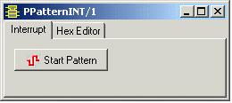
The two modes of transmission available are continuous and interruptable. The style of transmission can be set as single or repeat. The parallel pattern varies according to the mode and style of transmission chosen. For interruptable mode, the Start Pattern button has to be clicked each time for individual byte transmission. The initial state and duration for a byte transmission can be varied.
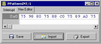
On clicking Setup, an editor window pops up. This window can be resized as required.
>In the window, select the Hex Editor tab and import the required *.BIN file containing data bytes in hexadecimal format and save.
<
Binary files that are already in the JOB folder can be edited and exported to .BIN format.
To simulate the model, select Simulation menu -> Analysis -> Transient analysis OR Oscillograph OR Logic Analyzer.
Each time the Start Pattern button is clicked, the data bytes will be displayed in a pattern that depends on the mode & style of transmission and other parameters specified.


Click here to view other Instrumental Models