Monostable Multivibrator
Aim
To design and simulate a Monostable Multivibrator circuit.
Components
|
Name
|
EDWin Components Used |
Description |
Number of components
required |
| BC107 |
BC107A |
Transistor |
2 |
| RES |
RC05 |
Resistor |
6 |
| CAP |
CASE-A600 |
Capacitor |
2 |
| DIODE |
1N4007 |
Diode |
1 |
| VDC |
VDC |
Dc voltage source |
2 |
| VGEN |
GEN |
Ac Voltage Source |
1 |
| GND |
SPL0 |
Ground |
3 |
Theory
A multivibrator in which one transistor is always conducting
(i.e. in the ON state) and the other is non-conducting (i.e.
in the OFF state) is called a monostable multivibrator. Monostable Multivibrator or one-shot multivibrator
has one stable state and one quasi-stable state. i.e. When one transistor is conducting and the other is non-conducting,
the circuit will remain in this stable state until the application of external trigger pulse
After a certain time the circuit will automatically switch back to the original stable state and remains there until another pulse is
applied.
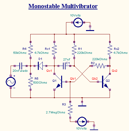
The circuit of a transistor monostable multivibrator is shown in the figure. With the above circuit
arrangement Q1 is at cut-off and Q2 is at saturation. This represents the stable state. The
base of Q1 is kept at a negative potential to ensure that it is always OFF
unless when trigger is applied.
The triggering network consists of the voltage source, the input
capacitor, R4, R5 and D1.

When a trigger pulse is applied, Q1 turns ON and the collector voltage
of Q1 drops from VCC
to the saturation voltage of 0.2V. This negative change is coupled to the base of Q2 by the capacitor which
inturn causes Q2 to turn OFF. This represents the quasi-stable state. Now
the capacitor starts charging towards VCC. When the
capacitor voltage reaches 0.7V, transistor Q2 turns ON and Q1 switches
back to the OFF state.
Procedure
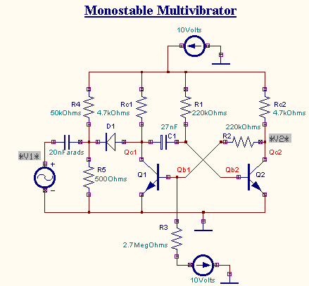
EDWinXP -> Schematic Editor: The circuit diagram is drawn by loading components
from the library. Wiring and proper net assignment has been made. The values are assigned for relevant
components.

EDWinXP -> Mixed Mode Simulator: The circuit is preprocessed. The desired test points and
waveform markers are placed. The Transient Analysis parameters have been set. The Transient Analysis is
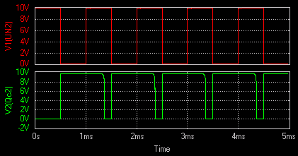
executed and output observed in Waveform Viewer.
Result
The output waveform may be observed in the waveform viewer.
