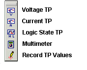
Test Points
To create a testpoint on the circuit.
Click on the connection/pin to assign the testpoint. The user can also click on another testpoint of the same type (voltage, current, or logic state) assigned already to the desired connection/pin. Move the small rectangle to the desired position and click the left mouse button again to place the testpoint.
There is no limit to the number of testpoints that can be placed on a project.

Voltage TP-F1
To create testpoints displaying analog net voltages.
Operation
Select this option tool and point to each circuit net. Place the Voltage Testpoint Display box by clicking at required nodes of the circuit net. The testpoint gets placed at the required place.
Current TP-F2
To create testpoints displaying currents flowing into component pins (connected to analog nets).
Operation
Select this option tool and point to each circuit net. Place the Current Testpoint Display box by clicking at required nodes of the circuit. The testpoint gets placed at the required place.
Logic State TP-F3
To create testpoints displaying currents flowing into component pins (connected to analog nets)To create testpoints displaying logic states on digital nets or on input/ output pins.
Operation
Select this tool and click on the input/output pins. The test point can then be placed by clicking the mouse.
Logic states
Logic simulation uses 6 values to represent logic states of digital nets and digital output pins
L Known logic low level state.
H Known logic high level state.
Z Known high impedance state.
X Unknown logic state that covers L, Z, & H.
D Unknown logic down state that covers L & Z.
U Unknown logic up state that covers Z & H.
Three among these are used to represent logic states of digital inputs.
L Known logic low level state.
H Known logic high level state.
X Unknown logic state that covers L & H.
To measure voltages, currents and logic states in the circuit after simulation.
Operation
The Multimeter modeless dialog box appears allowing to measure voltages, currents and logic states in the circuit after simulation. The multimeter has four modes of operation.
Voltage - Displays net voltage relative to the reference net and works only with analog nets. Click and hold down the left mouse button on the desired net.
Diff. Volt - Displays difference voltage between two analog nets. First click the left mouse button on the (-) net, then click and hold down the left mouse button on the (+) net.
Current - Displays current flowing into a component pin. Works only with analog pins and with digital pins connected to analog nets. Click and hold down the left mouse button on the desired pin. Positive value means current flowing into the pin, and negative - flowing out from the pin.
State - Shows logic state on digital nets or on input/ output pins. Works only with digital nets and pins. Click and hold down the left mouse button on the desired digital net or I/O pin.
Record TP Values
Applies to:
Mixed Mode Simulator
Purpose:
This tool allows to save Tespoints placed for a particular database in an ASCII format.
Operation
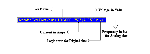
First select the testpoints and place it at the required nodes. After analysis, Click Save Testpoints from the drop down list of Testpoints . Now click the nodes for which the testpoint placed, are to be saved. The status bar figured below shows the format in which it is saved as a .TPS file, which may be viewed as a .TXT file.
