Convert truth table to diagram
This function enables conversion of digital logic coded as truth table into schematic diagram.
Conversion procedure is divided into three steps using dialog invoked from menu Tools - > Convert truth table to diagram.
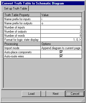
Step 1 - Setup of truth table properties and selection of processing options.
The truth table consists of an array of binary words containing input and output states. The number of inputs is limited to eight while the number of outputs must be equal to or greater then zero. Number of words in both arrays is limited to 2 to the power of (number of inputs), but may be set to lesser number.
Inputs and outputs have settable name prefixes and are numbered from 0 to n, where ‘i0’ and ‘o0’ are least significant bits in the word.
Each array element may be in one of the three states; ‘0’, ‘1’ or ‘X’. For readability, the states may be presented in any of the selectable conventions as shown:
The truth table is converted to schematic diagram, which may be included in the project in three ways:
- Diagram may be appended to currently edited page.
- Diagram may be appended as a new page in currently selected circuit.
- Diagram may be added to the project as a new sub-circuit. Names of inputs and outputs are used as names for input and output nets of the sub-circuit.

Components in the diagrams resulting from truth table conversion may be automatically placed according to selected placement in the schematic. The nodes connecting wires are automatically routed. These automatic functions are optional. Diagrams where auto placement option is deactivated cannot be auto routed.
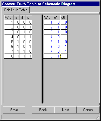
Step 2 - Editing truth table.
Clicking ‘Next’ button opens dialog for setting states for inputs and outputs. All possible states of inputs are automatically generated. By default the states of all outputs are set to ‘X’ state. Clicking on each cell representing array element allows changing states of inputs and outputs to desired one from a menu that pops up.

Analogically, contents of a whole input or output word may be entered by clicking in the cell in first column where word number is displayed.
Step 3 - Finishing conversion.
When all the desired states of inputs and outputs have been set, clicking ‘Next’ button will result in truth table conversion to schematic wire list format. The file with wire list is stored in a temporary folder under fixed name ‘True TableNetlist.wrs’. Listing of this file may be invoked from the dialog that pops up when conversion is successfully completed. This dialog allows setting finishing options for processing of diagram - like page format and parameters for automatic topological placement of components.

After clicking ‘Finish’ button, the netlist is imported, component placed and connections routed. The new diagram is blocked and may placed in desired position on the page.