Routing the Board
Connections between components may be established by using
TRACES and COPPER POUR areas. Click
Route from Tools toolbar to enable a set of Routing tools on right clicking
the workspace.

Adjust zoom precision to view the pins properly.
Turn on Preference/ Guidelines (Next unconnected node) before routing because
this option guides you to take the easiest path to route.
Select True Size and Pad frames from View/ Layout, enabling you to select proper
trace size. This also prevents you from creating errors such as traces crossing
over pad, traces very close together etc.
First route power and ground signals (Net SPL0 and +5V). In Project Explorer,
select Project / Project Design Rules and set the routing width to 0.030”
for Pwr/Gnd lines and 0.013” for Signal lines.
To start routing traces, first select the power points; say pin 14 of U1 and
route to pin 14 of U2.
The steps to complete this connection are as follows.
The trace connection may now be created in the following way.
1. Right click and enable tool
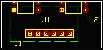
Route to start routing connections. Select layer for routing from Layers in the main menu. 28 layers are available for routing. By default COMP LAYER is selected. Click on pin 14 of U2 to route on SOLD LAYER. A small triangle appears at this pin and cursor changes to a crosshair with a square. The next node in that net is displayed with ratsnest ending with a rectangle as shown in Fig.8.3.


Toggle arc insert (F11) to change routing directions in arcs.

Fig.8.3
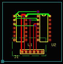
2. Move cursor with 45° angle through a short distance and click at the nearest point as shown below. The first segment has now been anchored. Now take this trace horizontally and click near 14th pin of U1. Once again take bend point at 45° angle and connect the trace to 14th pin of U1.

Fig.8.4
3. Terminate routing of the trace by pressing END or F4 key on your keyboard. Or click on the tool
End Connections.
4. Connections of 5V net have been accomplished by traces. The Ground net connections can be done by using a copper pour area. Select
Copper from the Tools toolbar. Select the second Function tool
Create Copper graphic item and select the fifth option tool
Create copper pour area. Now select the net to which the copper pour should belong by selecting SPL0 from the dropdown list box
in the Sizes toolbar. Now start creating the copper pour polygon by clicking near the 7th pin of U1. Clicking on any point introduces a vertex at that point. Enclose the 7th pin of U2 and the entire connector, then right click and press
Finish Copper Pour Create.

Fig.8.5
5. Semi-autorouting functions can also be used to route connections. Select the function tool
Auto Connect Traces. Select the first option tool
Auto Connect Node Pair and click on the 2nd pin of U1. A rubber band like connection shows where it has to be connected as shown in Fig.8.6.

Fig.8.6
Click on the node where the rubber band connection ends, i.e. pin2 of U2 and the connection is automatically routed, now press
End Connection.

Fig.8.7
6. Uses the second option tool
Auto Connect net to autoroute a net. Click anywhere on the workspace, an input box appears, enter the name of the net, which has to be routed, say A. Clicking on a node belonging to the net A will also achieve the same result (i.e. clicking on pin 1 of U1).
7. Repeat the same procedure as in (5) for the nodes at pin 3 of U1 and U2 respectively as well as the rest of the unconnected nodes on the connector.


Fig.8.8
To avoid errors
1. While routing, click on pins and then enable the tool
Pin to pin. This will allow routing between pins and ensures proper connection.
2. Routing between pads should be done carefully, else trace connections get merged to the pads thus producing errors. This may be avoided by enabling True size ON from View menu, thus while routing the board; trace-pad distance may be noted and changed.
Assign Nets
Entry points having electrical connections in schematic are highlighted as nodes in the layout. Net is a collection of nodes that are electrically connected together. The creation of a trace automatically results in creation of the corresponding Net. A trace is merely a visual representation of the corresponding net description.

Creating Nets
User can create a Net connecting the desired entry points using the available tools. The system by default assigns name to each net (E.g. UN1, UN2 etc. - UN stands for UNNAMED) and these may be edited or renamed according to user’s convenience.
Net Names
The default net names (UN1, UN2 etc…) assigned by the system may be renamed according to the function it performs. System allows naming the net as PWR/GND, NAMED (RESET, CLOCK…) and UNNAMED nets (UN1, UN2....).
Advantages of using Net names:
i. Editing the nets in complex project becomes simpler.
ii. Net names indicating the function makes job easier in identifying the nets and is helpful while simulating the circuit.
iii. The other advantage of NAMED nets is that while working with complex circuit, a different designer would come to know the status of the net to be NAMED net, so that this information prevents that user from tampering the net name.
Default Nets
The power and ground pins are assigned to the part at the time of part creation. These are referred as SPL1 and SPL0 respectively and are called the Default Nets. After packing components in the schematic, these nets are automatically represented as nodes in the layout.

Net Priority
Priority is first given to PWR/ GND, then NAMED nets and then to UNNAMED nets. While merging, when a NAMED net is merged to UNNAMED net, the resulting net has the name of the NAMED net. In the same way, when a PWR/ GND net is merged to NAMED net, the resulting net has the name of the PWR/ GND net.
Incase of nets having the same priority, the second net selected gets merged into the first net; i.e. if two UNNAMED nets UN1 and UN2 are to be merged, and if UN1 is first selected and then UN2, the resulting net has the name UN1.
Autoroute Traces
A set of tools has been provided to automatically route the traces between selected nodes and selected net. Autorouting can be done by either using the function tool Autoconnect Traces or by using any one of the three available autorouters.
How to route using the function tool?
i. Select the function tool
Autoconnect traces.
ii. To autoconnect selected nodes of a net, select the option tool Auto Connect Node Pair. Click on any node of a net. The trace gets connected to the node and remains tagged to the cursor showing a connection to the next nearest node of the selected net. Move the mouse to the next node and continue this process till the last node of the selected net is connected. END key completes the current routing action. This is a semi automatic process.
iii. To connect a selected net, select the option tool Auto Connect Net. Click on any node of a net. A confirmation box pops up confirming the route. Click Yes to route the trace. All nodes of the selected net get routed.

How to use Arizona Autorouter?
Select Auto?Autorouters ?Arizona from the Layout editor menu bar.
The function toolbar of Arizona autorouter is explained below:
Parameters setup
Routing Parameter Setup
This option pops up Routing Parameter Setup to set routing directions for the selected layer, set clearances between pads, vias and traces, setup routing scheme and wrong layer cost for the design, to set trace width & to select via padstack for Pwr/ signal connections, set fanout routing parameters, setting optimize costs parameters such as Trace right direction, Trace wrong direction and Vias. Toggle ON/OFF routing of Pwr and/or signal connections. If the settings in Default Design Rule dialog is to be used, then enable the options provided.
Routing net parameters
This option pops up Net Parameters to set routing parameters for individual nets & net groups. Click on each net to pop up Design Rule set dialog where the necessary options may be set.
Interactive routing
Selected pad pair
Option to route traces for selected pad pair.
Delete & reroute selected trace
This option tool allows deleting a single trace and rerouting it again.
Selected component
This option tool allows to route all traces connecting selected component.
Delete traces of selected component
Option to delete all traces connecting selected component. With this tool selected, click on the component whose trace connections are to be removed. All the routed traces of that particular component get deleted immediately.
Fanouts for selected component
Option to preroute fanouts for selected component. Select this tool and click on the component whose fanouts are to be prerouted. The escape wires for the components gets prerouted.
Fanouts for selected net
Option to preroute fanouts for selected net. Select this tool and click on any of the nodes of the net whose fanouts are to be prerouted. The escape wires for all the pads in the net gets prerouted.
Fanouts for selected SMD pad
Option to preroute fanouts for selected SMD pad. Select this tool and click on the SMD pad whose fanouts are to be prerouted. The escape wires for the selected pad gets prerouted.
Auto routing routines
Fanouts on whole board
This option tool allows to preroute fanouts for whole board. When this tool is selected, the escape wires for all the components (for the entire board) gets prerouted.
Start autorouter
Option to start router in full auto mode. This option tool when selected starts the execution of the autorouter. Routing is done according to the settings made. The status bar shows the percentage of completion of the routing.
Remove redundant vias
Option to remove redundant vias. On selecting this tool, the redundant vias are removed and the whole trace gets re-routed in a single layer.
Clean up
Option to clean up the design after routing. After routing, selecting this option tool optimizes the layout project by deleting the unnecessary trace loops or trace segments, which have been created.
Test for conflicts
Option to remove clearance and route rules conflicts. Select this tool after routing. The number of traces tested and number of traces found OK. Are shown in the status bar at the bottom. In case any contrariety is found with the traces, they are removed. The traces thus removed can be identified using the tool Display list of unrouted pairs. The routing may be done anew to get rid of the contrarieties.
Optimize
Option to optimize routed results taking into consideration, the optimization cost parameters and the weight of the traces, which result. During optimization the router tries to reroute every trace and if it gets weight of new trace less than previously routed then it deletes old trace and puts new one to the project, otherwise nothing to be done.
To remove as much vias as possible 'Via Cost' should be setup as at least 1000.
List of unrouted pairs
This option tool displays the list of unrouted pairs in the design. This option tool when selected pops up a dialog box listing the unrouted pairs. The copy screen to clipboard button may be used to copy the list of unrouted pairs in case it is required for say, verification purposes.
Miter
Option to miter all orthogonal traces & finish autorouting. When this tool is selected, a dialog box pops up to confirm the mitering operation because once it is executed; re-entry to the autorouter is not allowed.
