Board Analyzers
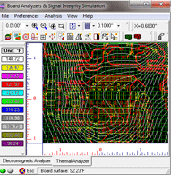
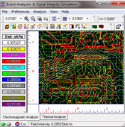
EDWinXP provides two board level analyzers. The Thermal Analyzer is intended to be used for analyzing and identifying potential thermal problems on a Printed Circuit Board. The Electromagnetic Analyzer is used for understanding the distribution of Electric field intensity over a routed PCB. Signal Integrity Analysis allows you to calculate how substantial the signal gets distorted while it passes through the selected trace.
Thermal Analyzer

Thermal Analyzer is an application that allows analyzing the effects of temperature parameters in the functioning of the circuit. The thermal effects generated by the board parameters, component parameters, cooling parameters etc. may directly influence the working of the circuit. The analysis can be done with the parameters set to the required values and the analyzer does the analysis taking into consideration the effects caused by these parameters. The Thermal Analyzer contains a full set of functions for setting the different parameters, running the analysis and displaying the result of the analysis using isotherms or color mapping scheme.

Electromagnetic Analyzer

ED-EMA is a tool to calculate and measure the magnetic radiation of your PCB design. Thus, to help you save money on costly manufacturing steps, until you get an acceptable design and to help you comply with the EMC rules for CE certification and to maintain a proper documentation. Find out about Crosstalks, Improper placement, Shieldings and more when your design is still a design. Save your results for your documentation.

ED-EMA is a true 32-bit application that runs on all Windows platforms. Special compliment to EMC users - Signal Integrity - is an add-on option available which is used to check the integrity of an electromagnetic signal as it passes through a trace from one pin to another pin. Thus predicting, how a signal deviates from its ideal (or intended) behavior in a real-world setting. The simulation result will be graphically presented using the Diagram Generator. The Field Analyzer is a tool for studying the electromagnetic fields that are created when power and/or signal traces on the board are energized.
Signal Integrity Analyzer
The Signal Integrity Analyzer examines the probable distortion of high-speed signals as they pass through traces on the PCB.The Signal Integrity Simulation tool is a plug-in extension to the EDWin - Electromagnetic Analyzer. It is intended to aid the designer in analyzing and understanding the interactions between the various signals on the PCB being designed (cross talk). Using the information obtained from the Signal Integrity Analyzer, the designer can make appropriate decisions about the various signals (distortion) on the PCB, so as to realise an electromagnetically compatible system, with adequate signal quality, in the shortest possible time.
Product Features:
Analysis Capabilities
- User defined choice of Nets and Test Points for Simulation
- Sandwich (multilayer) analysis and full board testing (all nets)
- Facility for simulating only time intervals of interest
- Transmission Line based modelling
Simulation Features
- Handles all IC technologies
- Built-in, generic, technology-specific models for IC pin I/O characteristics
- Built in templates for common signals
- Facility for specifying piece-wise linear, complex signals
Post-processing
- Results are post-processed and graphically presented using the Waveform Viewer
- Results may be saved and re-examined at any time
- Multiple results may be viewed simultaneously for comparing various analyses
User Interface
- Plugs in seamlessly into the EDWin Electromagnetic Analyzer
- Intuitive, Graphical User interface for specifying all parameters and simulation criteria
Software requirements
- EDWin Electromagnetic Analyzer
Field Analyzer
The Field Analyzer is a tool for studying the electromagnetic fields that are created when power and/or signal traces on the board are energized. The results of the analysis may be viewed as Color Graph, Isoline Graph,Field Direction Graph,Polar Cordinates Graph and 3D Wire Mesh Graph. The Field Analyzer examines electromagnetic phenomena inside and outside the boundaries of the PCB. It's output shows dynamics of the field's variation over a specified period of time. Once the analysis starts, information about the field is dynamically presented in two ways:
1. The Field display area will show variation of the selected field type using the graph type specified.
2. Depending on the current choice, the Waveform display area will show either
- The time variation of the amplitude of the selected field type or
- Its spectral content at that moment.