Serial In Serial Out Shift Register
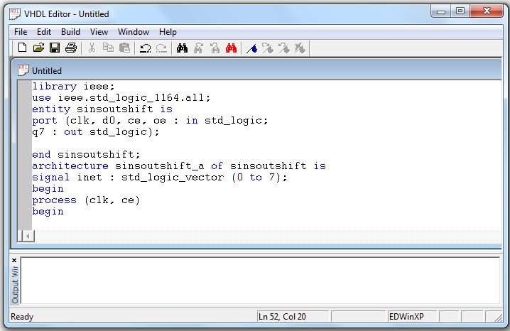
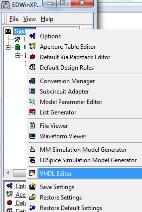
- Right Click on System from Project Explorer and select VHDL Editor from the List
- Enter the following code in the workspace provided in the VHDL Editor window
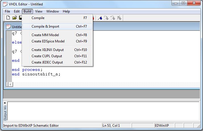
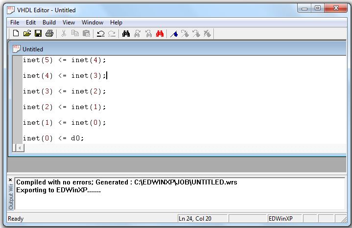
- Save the file (.vhd) and compile the code using Compile & Import option from Build menu.It compiles the source file and generates wirelist (*.wrs) output file
- Output window shows the status of errors
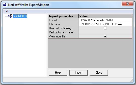
- Click on Import button in Netlist/Wirelist Export&Import window.
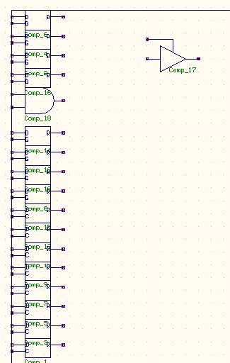
- Open Schematic Editor,Autoplace components by selecting Tools|Autoplace.
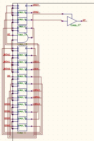
- Autoconnect components by selecting menu Tools|Connections.Select option tool Autconnect all wires from Connect components
- It is not possible to create Pcb layout of a schematic using vhdl as its component part includes only symbol hence couldn't pack components.
library ieee;
use ieee.std_logic_1164.all;
entity sinsoutshift is
port (clk, d0, ce, oe : in std_logic;
q7 : out std_logic);
end sinsoutshift;
architecture sinsoutshift_a of sinsoutshift is
signal inet : std_logic_vector (0 to 7);
begin
process (clk, ce)
begin
if ce = '1' then
if (clk = '1') and (clk'event) then
inet(7) <= inet(6);
inet(6) <= inet(5);
inet(5) <= inet(4)
inet(4) <= inet(3)
inet(3) <= inet(2);
inet(2) <= inet(1);
inet(1) <= inet(0);
inet(0) <= d0;
end if;
end if;
end process;
process (ce, oe)
begin
if (oe = '1') and (ce = '1') then
q7 <= inet(7);
else
q7 <= 'Z';
end if;
end process;
end sinsoutshift_a;